Bubblegram / Laser Crystal LED Stand

When I visited the European Space Center earlier this year I picked this cool bubblegram of the planets in our solar system. I decided to make a base for it so I could light it up with some LED’s.

IMG_20190512_220624472

I decided to get with RGB LED’s so that I could have the colour change over time. Making a circuit for one of these was easy enough. I used 3 x 220 ohm resistors for each of the three anodes on each LED.

IMG_20190512_220629270

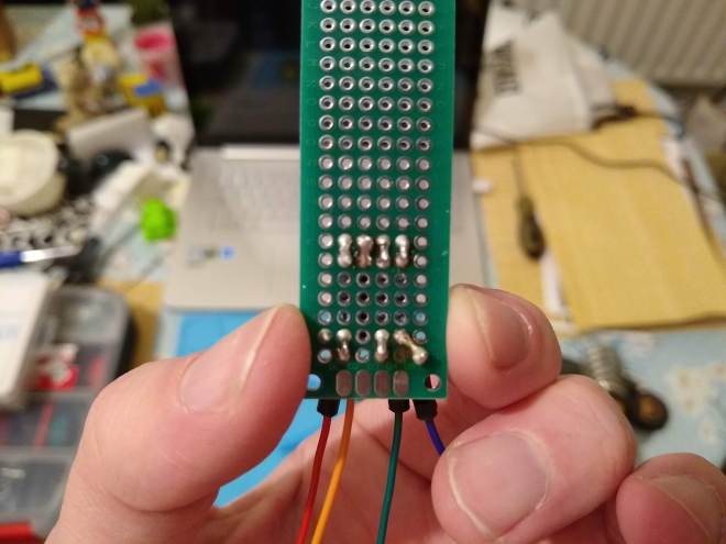
I soldered the resistors to the LED and added cables for the anodes and cathode.

IMG_20190513_184324847

An Uno board was used to test the LED. pins 9-11 (PWM pins) were used to control the colours and brightness. By altering the PWM width for each colour the brightness of each colour and thus colour mixing can be controlled.

screenshot

Next I set about designing the 3D model of my stand. I created a block the size of the bubblegrams I have and added a rim round the outside to hold it in place. I hollowed out the middle to make room for the electronics and cut a hold in the side for the power plug.

The stand is available on Thingiverse https://www.thingiverse.com/thing:3633780

IMG_20190514_181635620

There is no way an Uno board would fit in the stand so I picked up a Nano to use instead.

IMG_20190515_181021643

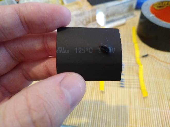
Before squeezing the electronics into the case I decided to wrap the RGB boards I had made in shrink wrap to prevent them shorting out if press against the other boards. A hole was cut for the LED to poke through.

IMG_20190516_071750439

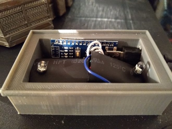
The electronics were crammed into the stand. They literally just fit!

The LEDS were programmed to cycle through different colours in a loop.

The scripts I have written to do this to are available on my GitHub page. https://github.com/shane-powell/led-lighting


Raspberry PI Rover Upgrades

I recently picked up the Pimoroni Garden hat and some sensors to play with as it looked like a neat way of swapping breakout boards around without wiring or soldering.

Soon after I thought why not upgrade my rover with the hat so it can drive around measuring air quality, temperature etc… Then I remembered I had my phat stack board lying around and the project turned into lets see how many hats I can stack on the rover.

20181110184604 
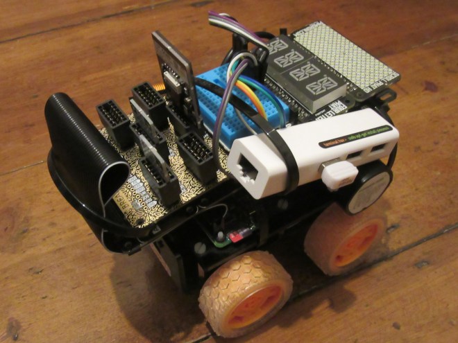
So first I added the phat stack with the breakout garden hat, explorer (motor) phat, four letter phat and a scroll phat HD. For convenience I also attached  USB hub / Ethernet adapter. This makes it easier to work on the PI if there are any Wifi issues.

20181110174541

I tested everything worked and whilst being blinded by the scroll phat I had the idea of using it as lighting for the front mounted camera. Continue reading Raspberry PI Rover Upgrades

Raspberry PI LED Matrix Games

A while back I brought a new hat for the Raspberry PI called the unicorn hat HD. Its a 16 x 16 led matrix (256 LEDs) which I managed to get cheap while it was discounted.

I started playing with it recently and at first tried to use it as an over head minimap in mine craft. This kind of worked but the mine craft API was too slow to feed it data quick enough. All well and good if you only stood in one place but useless otherwise.

Next I thought I would try building some pixel games and have been working on a little space invaders clone.

The game is written in python and uses the pygame package for keyboard input but if it were to use something else for input like GPIO pins then pygame could be ditched.

I need to get my head round drawing text to it so I can make a game over screen etc…

You can clone the code here: https://github.com/kenjara/Unicorn-Hat-HD-Games

space1

My First Arduboy Game

The Arduboy is a tiny Arduino powered handheld console that you can use to create your own games or download and play other peoples. I have wanted one ever since I first saw it on the Pimoroni store as I like doing a bit of game development from time to time and the nature of the device would keep the projects small and manageable. Continue reading My First Arduboy Game

Meet My New Robot

I finished building my robot today. It was a comparatively quick build compared to RC and model kits I am used to making.

I will make a full post of the build and the technology behind it later but for now here is a video of me calibrating the servos that control the robots head.

I needed to find the right values in order to make sure the robot looks where I want it to.

The robot uses a Seeeduino which is an Arduino compatible controller board and has ultra sonic sensors for eyes.