Airfix SR-N1 (1973)

Here I am building the Airfix SR-N1 hovercraft.

According to the box I have and the internet this is the 1973 release making it by far the oldest kit I have ever brought and made. The kit itself does not have many parts but due to its age and condition it was not the easiest build.

IMG_20181020_132755
The kit came from eBay and cost a lot more than £15 it seems to be pretty hard to get hold of one now

IMG_20181021_144733

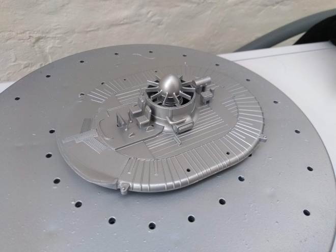
I started by putting the chassis together and the associated parts that were all to be painted aluminium. I had to use a fair amount of model filler to fill the gaps between the bottom and top of the chassis. This was then spray painted.

IMG_20181022_195146

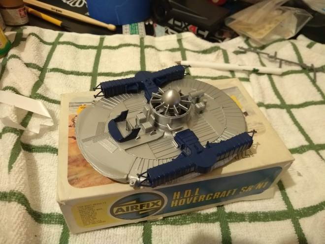
The parts to be painted blue were sprayed and test fitted to the model.

IMG_20190827_203639667

The window screen is glued onto the cockpit and parts of it are hand painted blue. This was the worst part of the kit. Neither part lined up and the cockpit was damaged. I had to use a mixture of cutting, filling and sanding to get these parts to glue nicely together.

The duct is painted white and attached to the top of the lift chamber.

IMG_20190830_081210694

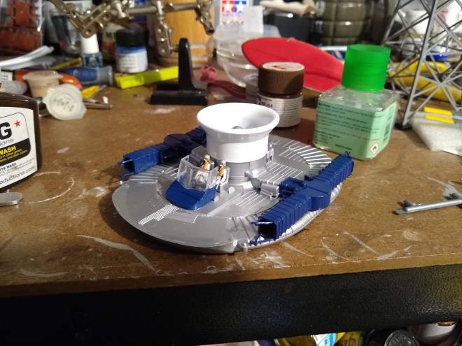
The crew are painted and added glued to their seats. They both have life jackets, helmets and masks.

IMG_20190830_120146949

The supporting posts and roof are glued into place completing the cockpit.

IMG_20190827_212104309

The decals were very yellow so I used the old trick of leaving them on by a window for a few days so that the light whitens them.

IMG_20190902_174931990

This is how they looked after a few days in the sun.

IMG_20190903_072719103

Next I started to apply the decals to the rudders, these were tricky as the decals were larger than the rudders meaning they either had to overlap of have the excess cut off.

IMG_20190903_182303756

The hovercraft with rudder decals and cockpit decal applied. The exhaust is painted black and the fire extinguishers are painted gold.

IMG_20190916_183905440

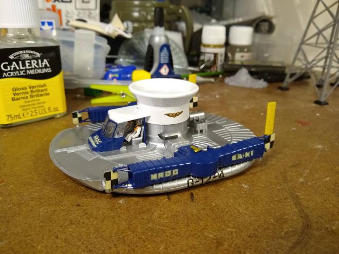
All decals have now been applied and the frame of the cockpit window has been hand painted blue.

IMG_20190907_195116733


Apollo 11 Astronaut 1/8 Scale

Being a bit bored of making military vehicles and a big fan of space exploration I picked up a couple of kits for the Apollo 11 50th Anniversary. This is the Revell Apollo Astronaut, I thought it would be an interesting kit as it will be the first time I have built a kit focused on a figure that size.

Continue reading Apollo 11 Astronaut 1/8 Scale

Bubblegram / Laser Crystal LED Stand

When I visited the European Space Center earlier this year I picked this cool bubblegram of the planets in our solar system. I decided to make a base for it so I could light it up with some LED’s.

IMG_20190512_220624472

I decided to get with RGB LED’s so that I could have the colour change over time. Making a circuit for one of these was easy enough. I used 3 x 220 ohm resistors for each of the three anodes on each LED.

IMG_20190512_220629270

I soldered the resistors to the LED and added cables for the anodes and cathode.

IMG_20190513_184324847

An Uno board was used to test the LED. pins 9-11 (PWM pins) were used to control the colours and brightness. By altering the PWM width for each colour the brightness of each colour and thus colour mixing can be controlled.

screenshot

Next I set about designing the 3D model of my stand. I created a block the size of the bubblegrams I have and added a rim round the outside to hold it in place. I hollowed out the middle to make room for the electronics and cut a hold in the side for the power plug.

The stand is available on Thingiverse https://www.thingiverse.com/thing:3633780

IMG_20190514_181635620

There is no way an Uno board would fit in the stand so I picked up a Nano to use instead.

IMG_20190515_181021643

Before squeezing the electronics into the case I decided to wrap the RGB boards I had made in shrink wrap to prevent them shorting out if press against the other boards. A hole was cut for the LED to poke through.

IMG_20190516_071750439

The electronics were crammed into the stand. They literally just fit!

The LEDS were programmed to cycle through different colours in a loop.

The scripts I have written to do this to are available on my GitHub page. https://github.com/shane-powell/led-lighting


Tamiya Isuzu mu

I recently took my CC-01 Isuzu Mu on holiday with me. Here’s a short video and some photos of it in action.

The CC-01 has easily become my favorite Tamiya chassis. It runs well out of the box without hop ups and gives a great scale look. The only thing I changed in mine was to use a 55t motor.

x500 independent lift conversion

IMG_20190218_182334861

Back when I received my x500 kit from Palaform it arrived with a lift duct to play with. I decided not to use it at the time as I just wanted to build the kit as standard but I decided it was time to experiment with it.

IMG_20190218_201417860

I started by deciding on the location of the duct  and making it out with a compass. I cut Continue reading x500 independent lift conversion

Open RC F1 Improvements

Front Axles

As seen in my last post there were a few issues with my open RC build that needed resolving. The first was the front wheel axle snapping. I have since printed a whole collection of front axles with 100 % infill (solid). This makes them much stronger than when they were only 20%. As I printed a whole bunch I have spares at the ready if I need them.

IMG_20190216_133119840


Steering

The next thing to look at was the steering. Here I was having issues with the servo not centering the wheels with no input. This indicated there were binding issues but it seems the servo may have also been at fault. While playing with the trim settings on the transmitter the servo went crazy and melted itself. There was a lot of smoke coming out so I quickly ripped out the Lipo battery and took the car outside. The house stunk of burnt electronics.

IMG_20190216_133553988

The offending item was removed and remarkably caused no warping to the PLA chassis.

IMG_20190216_144047810

I fitted a new servo and adjusted how the servo linkage worked to make the wire straighter.

IMG_20190216_152137592

I also used  a multitool to sand down the inside of the car body so that the servo rod no longer snagged on it. Lastly I added a washer between the servo saver and lower chassis.

These things combined have fixed the steering issues I was having. The steering now centers itself and responds a lot better than before.

Tyres

I have been having a lot of fun printing TPU tyres at different settings and have made some progress with regards to producing tyres with more grip.

IMG_20190216_153849949

That said the TPU tyres always lacked the grip of a rubber tyre so I caved in and brought some Tamiya tyres. I will go back to TPU when making a heavy vehicle as part of the problem is that the f1 car is so light the tyres are not creating much friction with the ground.

IMG_20190217_130634631

The Tamiya tyres. I had no idea that these came in different compounds so I ended up with super soft rear tyres and standard front ones.

IMG_20190217_203549525

New rims had to be printed for the Tamiya tyres and the wheel ends up a bit bigger than the printed tyre version. You can see that the rear tyre almost touches the bargeboard. This is good as it increases ground clearance a little which should lead to less damage when driving over uneven terrain.

I have only tested the Tamiya tyres indoors at the moment on wooden floor but I can already tell they perform miles better than the TPU tyres. I did make a second video however of my second generation TPU tyres at the weekend. These were a step up from my previous attempt which were much too hard. These are printed at 10%. I still have not had much success with printing them at 5% at all.

Next time with the rubber tyres the lack of grip should be a thing of the past!

Open RC F1 Test Run

So above is a video of my printed F1 cars first outing. For the most part it works pretty well but there are a few teething issues to sort out.

First the tires I have printed have no grip. I printed them with far too much infill and they are no where near soft enough. I do not want to give up and go to Tamiya tyres so will be playing around with reducing the infill and making these softer.

Secondly as you can see in the video the front axle snapped, I have reprinted a whole tray of these solid so the next ones will be stronger and if not I now have spares.

Lastly its not very noticeable in the video but my servo pusher is rubbing up against the body shell and causing the steering not to return to center. This should be easy to fix but I need to unscrew the body first.

Open RC F1 3D Printed TPU Tyre

So the rest of my open RC F1 car is printed and it was time to get onto the most tricky part the tyres. The rest of the car was printed in PLA but the Tyres need to be flexible so they are printed in TPU.

The TPU brand I purchased was Enotepad. It arrived in a box that looked plain apart from a logo that reminded me of good old word art. The filament felt flexible to touch so it was a good sign it was not PLA.

You can find my print settings at the end of the post.

MVIMG_20190205_225606983

My first print went horribly wrong because Continue reading Open RC F1 3D Printed TPU Tyre

Open RC F1 Car Part 1

I recently built a new 3D printer having wanted a bigger build bed and to go back to open printing. I went for the Ender 3 Pro which has turned out to be a great machine for the price.

I have always wanted to print and build an Open RC car but did not have a big enough print bed to print the parts. Now I do however so I thought it would make a good test for my new printer. All of this model apart from the Tyres will be printed in PLA. The Tyres will be printed in TPU so that they are flexible.

IMG_20190131_072732324 - Copy

The first thing I did was to try printing the chassis. I printed this with a bit more infill than the rest of the parts to make it stronger. The chassis parts and the rear axle holders were printed at 35% infill. Continue reading Open RC F1 Car Part 1

Raspberry PI Rover Upgrades

I recently picked up the Pimoroni Garden hat and some sensors to play with as it looked like a neat way of swapping breakout boards around without wiring or soldering.

Soon after I thought why not upgrade my rover with the hat so it can drive around measuring air quality, temperature etc… Then I remembered I had my phat stack board lying around and the project turned into lets see how many hats I can stack on the rover.

20181110184604 
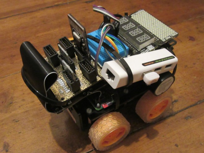
So first I added the phat stack with the breakout garden hat, explorer (motor) phat, four letter phat and a scroll phat HD. For convenience I also attached  USB hub / Ethernet adapter. This makes it easier to work on the PI if there are any Wifi issues.

20181110174541

I tested everything worked and whilst being blinded by the scroll phat I had the idea of using it as lighting for the front mounted camera. Continue reading Raspberry PI Rover Upgrades